It is a program designing
tool which is designed to show the process logic of any program. It is a
pictorial representation so it can be drawn on the paper only. It is free from
any particular programming language. The process logic shown by flow chart can
be implemented in any programming language.
The symbols used in flow
chart are as follows.
Symbol
|
Purpose
|
Description
|
Flow line
|
Used to indicate the flow
of logic by connecting symbols.
|
|
Terminal(Stop/Start)
|
Used to represent start and end of
flowchart.
|
|
Input/Output
|
Used for input and output
operation.
|
|
Processing
|
Used for airthmetic operations and
data-manipulations.
|
|
Decision
|
Used to represent the operation in
which there are two alternatives, true and false.
|
|
On-page Connector
|
Used to join different flowline
|
|
Off-page Connector
|
Used to connect flowchart portion
on different page.
|
|
Predefined Process/Function
|
Used to represent a group of
statements performing one processing task.
|
Examples: -
1.
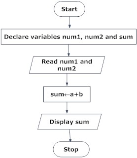
Draw a flow chart to input two no. and
add them.
2.
Draw flowchart
to find the largest among three different numbers entered by user.


This is great article.thanks for your approch.you can also check Studynote
ReplyDelete